Technology
- FSD
- Working Principles
- Adjustment
- Over-Under-Steer
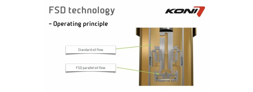
Introduction to FSD technology for cars
As a leading manufacturer of high performance shock absorbers, KONI develops the technical features of its front & rear dampers by following a simple principle: to meet the diverse demands on its products with sophisticated mechanical solutions.
The everlasting problems with vehicle damping
Vehicle damping has always been a compromise between comfort and road holding. An obvious example is a Formula 1 racing car which offers the best possible road holding but with minimal comfort. In a personal of sport car one expects to experience the ultimate in comfort, combined with safe road holding. Minimum damping is required for your comfort whilst strong damping is needed for safe and stable driving. This conflict of goals can not be solved with conventional front and rear dampers. Other damper systems, which are currently available in the market, do not offer an adequate solution:
No real alternative
- Position-dependent shock absorbers will give you extra comfort, as they allow for more movement of your car, but as a result, the road-holding is inferior. Sudden bumps in the road will still be very unpleasant.
- Pneumatic and electronic adjustable shock absorbers may improve road holding in the future. The disadvantage of such complex systems is that they are very expensive and time consuming to set up correctly.
Smart solution
KONl shock absorbers with Frequency Selective Damping (FSD) technology have been specifically designed for personal and sport cars and they combine the ultimate in comfort and road holding. The purely mechanical solution and thus the independence of electronic control components are the basis for the first choice of KONl FSD High Performance Damper if you have to solve the familiar everlasting problem.
Hydraulic Shock Absorbers
All hydraulic shock absorbers work by the principle of converting kinetic energy (movement) into thermic energy (heat). For that purpose, fluid in the shock absorber is forced to flow through restricted outlets and valve systems, thus generating hydraulic resistance.
A telescopic shock absorber (damper) can be compressed and extended; the so-called bump stroke and rebound stroke. Telescopic shock absorbers can be subdivided into:
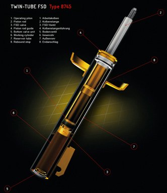
- 1. Bi-tube, or twin-tube dampers, available in hydraulic and gas-hydraulic configuration.
-
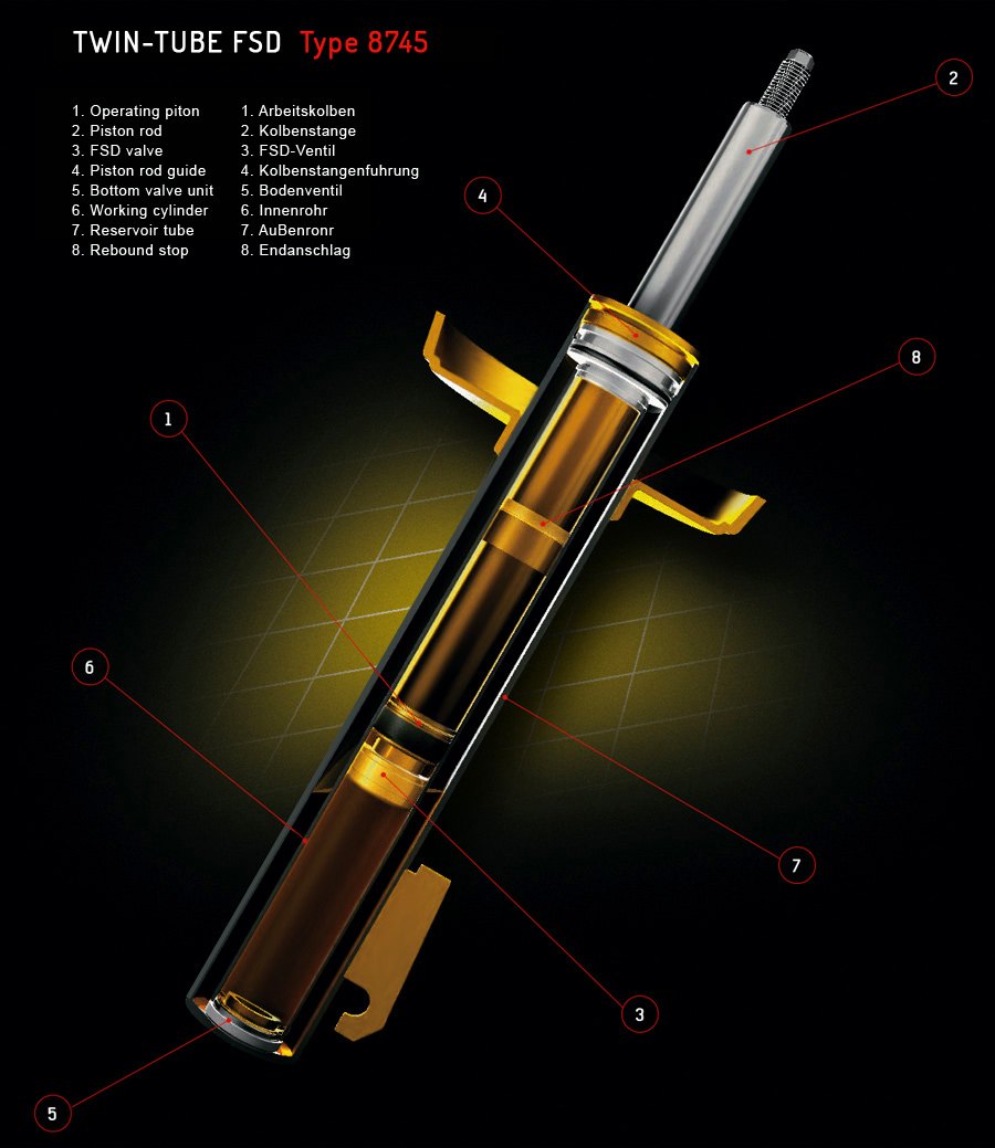
HOW DOES A BI-TUBE SHOCK ABSORBER WORK?
Bump stroke
When the piston rod is pushed in, oil flows without resistance from below the piston through the orifices and the non-return valve to the enlarged volume above the piston. Simultaneously, a quantity of oil is displaced by the volume of the rod entering the cylinder. This volume of oil is forced to flow through the bottom valve into the reservoir tube (filled with air (1 bar) or nitrogen gas (4-8 bar). The resistance, encountered by the oil on passing through the foot valve, generates the bump damping.
The main components are:
- outer tube, also called reservoir tube (8)
- inner tube, also called cylinder (7)
- piston (2) connected to a piston rod (3)
- bottom valve, also called footvalve (6)
- piston rod guide (5)
- upper and lower attachment
Rebound stroke
When the piston rod is pulled out, the oil above the piston is pressurized and forced to flow through the piston. The resistance, encountered by the oil on passing through the piston, generates the rebound damping. Simultaneously, some oil flows back, without resistance, from the reservoir tube (6) through the foot valve to the lower part of the cylinder to compensate for the volume of the piston rod emerging from the cylinder.
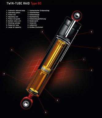
- 2. Mono-tube dampers, also called high pressure gas shocks.
-
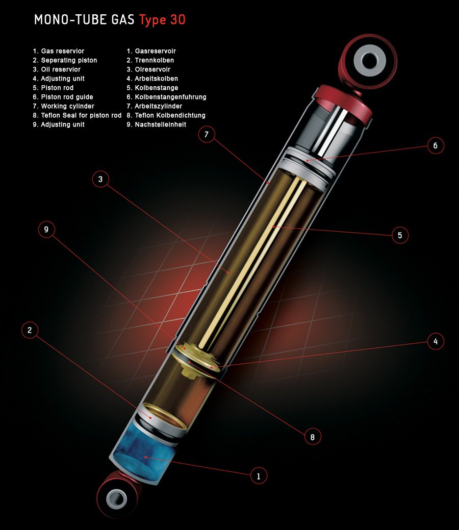
HOW DOES A MONO-TUBE SHOCK ABSORBER WORK?
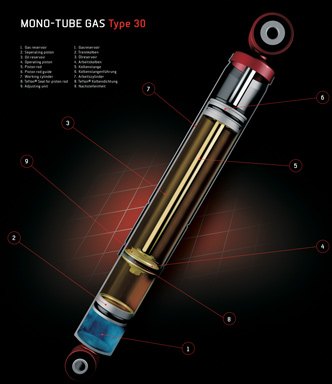
Bump stroke
Unlike the bi-tube damper, the mono-tube shock has no reservoir tube. Still, a possibility is needed to store the oil that is displaced by the rod when entering the cylinder. This is achieved by making the oil capacity of the cylinder adaptable. Therefore the cylinder is not completely filled with oil; the lower part contains (nitrogen) gas under 20 – 30 bar. Gas and oil are separated by the floating piston (2).
When the piston rod is pushed in, the floating piston is also forced down by the displacement of the piston rod, thus slightly increasing pressure in both gas and oil section. Also, the oil below the piston is forced to flow through the piston. The resistance encountered in this manner generates the bump damping.
The main components are:
- (pressure) cylinder, also called working cylinder (7)
- piston (4) connected to a piston rod (5)
- floating piston, also called separating piston (2)
- piston rod guide (6)
- upper and lower attachment
Rebound stroke
When the piston rod is pulled out, the oil between piston and guide is forced to flow through the piston. The resistance encountered in this manner generates the rebound damping. At the same time, part of the piston rod will emerge from the cylinder and the free (floating) piston will move upwards.
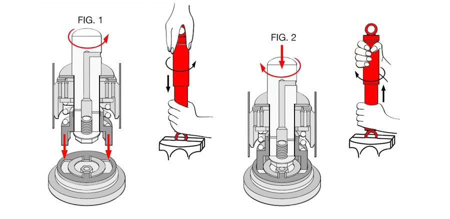
Adjustment of KONI shock absorbers
Rear and front struts – Series 76, 80, 82, 84, 86, 87, 88, 90, 92, 8040 and 8240
Adjustment procedures:
- Fully compress the left and right struts, at the same time turning the dust cap or piston rod slowly to the left (anti-clockwise), until it is felt that the cams of the adjusting nut engage in the recesses of the foot valve assembly. NOTE: Some shock absorbers include a bump rubber concealed under the dust cover and this must be removed prior to adjusting. Don’t forget to re-install.
- Keeping the struts absorber compressed, make 1 full turn (360°) to the right (clockwise). The total range is about 5 half turns.
- Extend the shock absorber vertically for at least 0.5 inch without turning in order to disengage the adjusting mechanism. The dust cap or piston rod may now be turned freely.
WARNING: Adjust both left and right dampers identically. Failure to do so may lead to unstable handling and uneven tire tread wear.
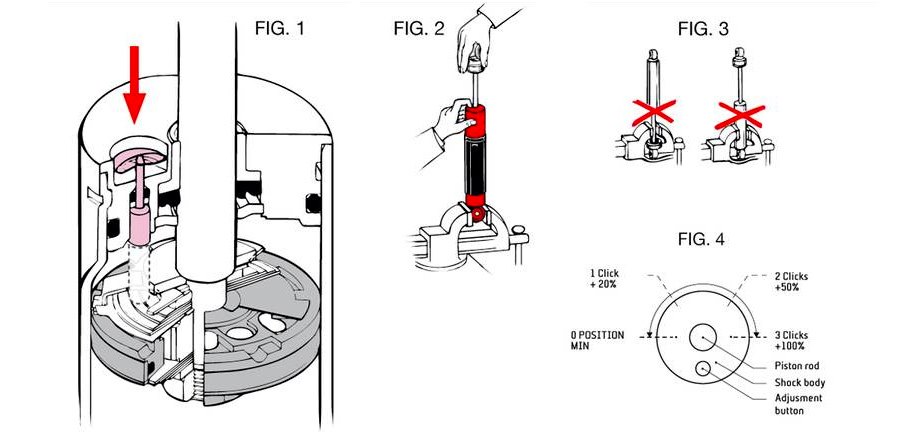
Shock absorbers – Series 26 and 30
Adjustment procedures:
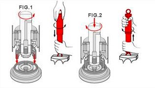
- Remove the plastic dust cover to expose the adjusting knob (fig. 2).
- Depress the knob fully and hold it in that position while adjusting (fig. 1 and 2).
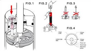
- The adjusting device has been provided with a number of distinct stops (clicks), each of which marks an adjustment position (fig. 4).
- To increase rebound-damping, turn the piston rod one or more clicks to the right (clockwise), and release the adjusting knob. DO NOT USE FORCE!
- Make sure that the adjusting knob springs fully back into position.
NOTE: 26 Series range limited to 2 clicks, 30 Series range limited to 3 clicks!
WARNING: Adjust both left and right dampers identically. Failure to do so may lead to unstable handling and uneven tire tread wear.

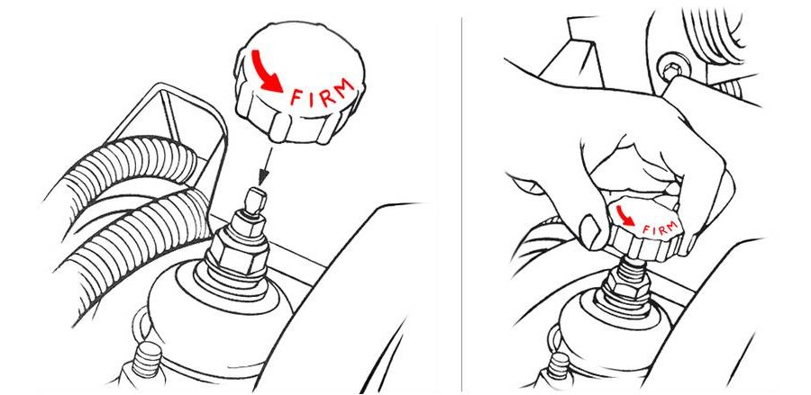
Rear and front struts – Series 8010, 8041, 8210, 8241, 8610, 8641, 8710 and 8741
Adjustment procedures:
- Take the adjustment knob which is supplied and fit it to the top of the dampers.
- To adjust the damping force, the knob has to be turned in the direction of the arrow for increased damping and to decrease in the opposite direction. If you feel resistance, do not use force as the damper is in its end position.
- After adjustment, remove the adjusting knob in order to prevent possible damage of the bonnet.
WARNING: Adjust both left and right dampers identically. Failure to do so may lead to unstable handling and uneven tire tread wear.
Car suspension related to on over / under steer
Over steer and under steer are two often misunderstood concepts related to the way a car handles. The following explanations and diagrams should clear up any confusion you may have.
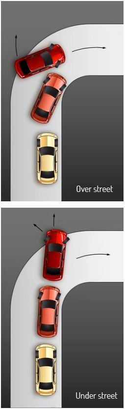
Over steer
Over steer is when the rear wheels are carving a larger arc than the front wheels or the intended line of the turn. Rear ‘slip angles’ exceed those of the front tires. This is often described as a ‘loose’ condition, as the car feels like it may swap ends or be ‘twitchy.’
This condition can be caused by ‘power over steer,’ where you need to reduce power in order to bring the back end back into line.
Under steer
Under steer is when the front wheels are carving a larger arc than the rear wheels. This is often described as ‘push’ or ‘pushing – as the front end feels like it is plowing off of a corner. Further acceleration only compounds the push, as weight shifts back to the rear drive wheels off of the front turning wheels, leading to a further lessening of the car's ability to turn in. Under steer can be remedied by slight modulation in throttle to transfer weight forward to the front wheels, aiding their traction and ability to carve the turn. Many cars are designed to have a tendency to under steer. If the driver gets uncomfortable and ‘lifts’ off the gas, that will cause the front end to tighten the curve – a relatively safer and more predictable condition. When the car's body leans in a corner, the outside suspension compresses and the inside suspension extends. In other words, the outside suspension moves in bump direction and the inside suspension moves in rebound direction.
Tuning Tips of your car suspension
If the car rolls on the rear outside suspension during corner exit, increase rebound damping force at the front inside. The front inside suspension affects the car mostly on corner exit. By adding rebound damping, you will loosen the car up on corner exit.
If the car rolls on the front outside during corner entry, increase rebound damping on the rear inside suspension.
By adding rebound damping to the front on both sides equally, it will tighten the car some. By adding rebound damping to the rear on both sides equally, it will loosen the car up.
Note that the shock absorbers do not change the amount of weight transfer, only the time it takes to transfer this weight.
Only adjust enough rebound into each shock absorber to eliminate the undesirable characteristic. Adjusting too much rebound may mask a handling problem of another sort and may even make things worse and dangerous.