
Frequently Asked Questions
- Why are sliding calipers bad?
-
Generally, most vehicles are equipped with 4-wheel disc brakes standard. A few years ago, you would be lucky to find disc brakes on all four corners. With performance vehicles, more and more are arriving brand new from the factory with monoblock calipers and are 4-pot. However, most vehicles on the street are still using sliding caliper mechanisms.
Sliding caliper mechanisms have certain drawbacks, most of which are examined here. In the picture, we see a typical set of used brake pads on a vehicle with a sliding caliper mechanism. A sliding caliper is a two-piece caliper with a single piston. Between the two pieces of the caliper are slider pins that allow the assembly to clamp down on the rotors.
The main drawback of sliding caliper brake systems is uneven pad wear, among other things. If the pads are not wearing evenly, then the sliders need to be cleaned and greased to ensure proper function.
The benefit of Megan Racing brake systems is that this sliding caliper mechanism is alleviated with a mono-block caliper construction. Instead of a single piston, piston size is smaller, but the quantity is increased to a 4-pot (4 pistons) or 6-pot (6 pistons) design for even pad distribution on the rotor.
This results in more consistent braking performance under extreme heat conditions, such as track use, more even brake pad wear and therefore increased longevity of the braking system. With the purpose of making a vehicle as efficient as possible, the big brake kits Megan Racing offers are an obvious choice for the next modification to your vehicle.
- Can I use shorter springs on my coilovers?
-
There is only 1 valid reason to ask for shorter springs: your lower bracket is not yet physically maxed out and the three locking spring perches are locked up against each other. A shorter spring would create more space between the top two and the third spring perch, therefore giving more height adjustment to go even lower.
- Pillow Ball Mount Information
-
On McPherson strut suspension (typical examples include 1989+ Nissan 240SX, Subaru Impreza 93+, Mitsubishi Lancer Evolution 8, 9 and 10, etc), the front strut is secured to the camber plate via pillow ball mount and typically the pillow ball mount is a universal application, which means the ID of the pillow ball mount is M14, for most of the coilover applications. However, there are a few isolated applications that use a special/unique pillow ball mount that is not the same as the rest.
There are seven different types of pillow ball mounts used:
- Standard, the most commonly used
- Honda Beat (international application only)
- 2000+ Toyota MR-S
- 1990 Toyota MR-2 / 2002-2006 Acura RSX (DC5)
- GDB/GDF Rear
- 1994 Dodge NEON Rear
- BMW E36/E46
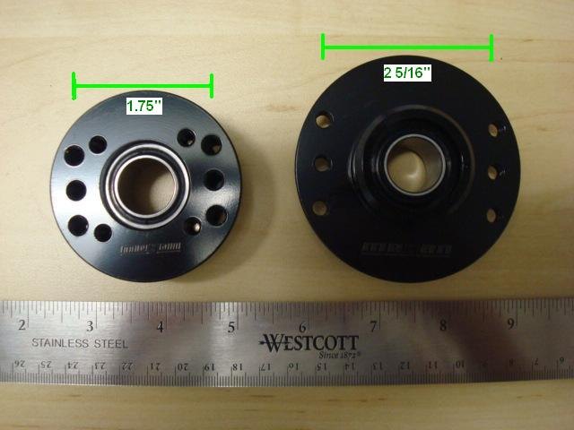
Pictured on the left (1.75") is one of the non-universal application pillow ball mounts, designed specifically for the 1990 MR-2 / Acura RSX DC5. Pictured on the right (2 5/16") is a universal application pillow ball mount that is most commonly used among the other applications. Notice the difference between the distance between the mounting holes. Aside from this difference, one of the main features of the unique pillow ball mounts is that the upper surface of the mount is flush while the universal mount is not.
This informational article is provided for your reference when purchasing replacement parts to help assure that you order the correct part for your application.
- Damper Setting Information
-
Car enthusiasts often ask questions regarding the best damper settings for their vehicle and for their intended use. It is often misunderstood that dampers have a “set it and forget it” setting. The truth of the matter is that they are adjustable for a reason, whether it be to make necessary damping adjustments to a spring rate change or to fine tune the handling characteristics of the vehicle. The topic of damper settings will be addressed in this article.
An important issue with the damper adjustments is how to find the settings. When in doubt, it is best to rotate the damper knob towards the STIFF setting by rotating the knob clockwise. There is a physical limitation towards the STIFF setting, while there is no physical limitation towards the SOFT setting, which is why it is extremely important not to exceed the amount of clicks going towards the SOFT setting as it may upset the shim-stack alignment within the strut or shock internals and result in damage to the damper internals. At this point, a third-party revalve may be necessary. Should the customer find a custom revalve of the shock necessary, Megan Racing offers shock cartridge insert replacements and often keeps these in stock for quick replacement for the customer.
To set the damper, Megan Racing suggests rotating the knob full clock-wise towards FULL STIFF and counting back the clicks counter-clockwise until you find the desired setting. For strut/shocks with 32-way adjustability, this means when the knob is adjusted to full stiff, you can count back 32-clicks to find the softest setting, but it is critically important for the life of the strut/shock that this limitation is not exceeded to prevent internal damage within the strut/shock.
First and foremost, all of Megan Racing coilover line-ups feature 32-way adjustability, except for their newest line-up, the EZ-Streets, which are 15-way adjustable. As stated in the product descriptions for the EZ-Street coilover applications, the valving characteristics between the EZ-Street Series and Street Series coilovers are the same, while the only difference being 15-way vs 32-way adjustability. This is simply to allow for finer damper adjustments should the user call for it. In essence, the max and min settings are similar (as long as they share the same valving code) and these would be reflected in the dyno plots provided for each damper, however one would take more clicks to reach the maximum and minimum settings compared to the other.
Changes between each click are sometimes so minute that you will not feel these differences back to back on the vehicle as there are several variables to consider when feeling for the differences. These would inevitably become apparent on an extensive dyno plot where the dyno is meticulously dyno’d at each individual click.
For the purpose of the general user with limited experience with adjustable shocks, Megan Racing provides a very generic outline of the damper settings:
1-8: Suggested for track use.
9-16: Suggested for mountain/aggressive use.
17-32: Suggested for common street use.
These settings are for generic purposes and should not necessarily be the end-all setting suggestion, but merely as a point of comparison to help you understand the nature of the strut/shock valving characteristics. With that said, while 1-8 is “suggested for track use,” you may find a softer setting to be more ideal for your particular vehicle, suspension setup, tire compound and driving style. Again, these are generic recommendations and should only be noted as a baseline.
To further understand the purpose of an adjustable strut/shock, one must understand exactly what it does. During the R&D phase of the development of a coilover damper kit, spring rates are chosen based on the front to rear weight distribution and the front and rear wheel motion ratios to determine the potential ride frequencies of the vehicle that would result from the selection of certain spring rates. Once the spring rate is determined for the particular application, the valving code is determined accordingly to handle the specific spring rate. The strut/shock valving deals primarily in controlling the spring, not necessarily the vehicle—again the spring rates are determined by factors of the vehicle, which is why some applications feature the same spring rate on all four corners, while some use heavier springs up front and some applications use heavier spring rates in the rear. In layman’s terms, the strut/shock’s sole responsibility is to critically dampen the spring oscillations and keep the spring under control during compression and especially during rebound of the spring. When a bump in the road is encountered, the energy of the wheel and suspension is transmitted to the spring, which causes the spring to compress a certain amount. This energy is stored in the spring during the compression stage of the spring and results in the decompression of the spring, or the lengthening of the spring back to free-length. The damper’s job is to absorb the energy transmitted from the compression of the spring to reduce extra oscillations of the spring that would inevitably be transferred to the vehicle resulting in undesirable handling characteristics.
Once these characteristics are well understood, let’s discuss how to properly tune the damper. For an intermediate user, tuning primarily for street use, the main thing to tune out for is making sure the suspension is not underdamped or overdamped, but critically damped. What this means is that the damping needs to be set to properly dampen the spring oscillations. If the spring is underdamped, the spring will continue to oscillate a few times after the initial compression. This results in a bouncy ride, which can be very uncomfortable and potentially dangerous. The overdamped situation can occur with the settings adjusted stiffer than what is necessary to control the spring oscillations. When the spring compresses and then rebounds, the shock is overdamping the spring and surpassing the spring frequency, which results in what feels like a stiff ride. Looking closer at an overdamped situation, the shock would be too aggressive for the spring and can result in loss of tire traction over rough and uneven surfaces by not letting the wheel conform to road undulations. This can be equally dangerous as sudden traction may be lost. This is critical to handling performance as an overdamped situation would result in less overall grip of the vehicle.
When one understands the concepts of a critically damped suspension, they will be able to further fine tune what the suspension is doing and further adjust the strut/shock damping to cater to their own driving preferences. Damper adjustments also have an effect on the handling characteristics of the vehicle as a whole and therefore also provide another means of tuning out understeer and oversteer tendencies. For advanced users, they may fine-tune the shocks to cater to their driving style, whether they prefer a more under-steer-prone vehicle or a more over-steer-prone vehicle. Of course, these understeer and oversteer tendencies are attributed to the entire suspension package and vehicle setup—not just the dampers. The dampers should be used to fine-tune the vehicle when everything else in the vehicle setup is tuned accordingly.
- Thread Pitch
-
Megan Racing has had several requests for the thread pitch of the shock bodies of their coilover assemblies.
The thread pitch for the Track, Street, Street-Lp, Ez-Street, and Euro Street coilover shock/strut bodies is: M50 x P1.5
The thread pitch on Top Pin is: M12 x P1.25
- The Internals of a Muffler Canister
-
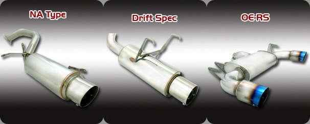
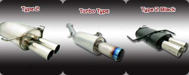
Have you ever wondered about the construction of a muffler? Well, now is your opportunity to find out. This is not the same for every muffler out there of course, because there will always be other designs that claim to flow better than others. The idea of a muffler is to reduce extraneous exhaust noise while keeping exhaust flow efficient. The inlet pipe diameter is the same throughout the muffler, however the internal pipe is baffled. This baffled pipe is then wrapped in steel wool which is then wrapped in fiberglass. Here is an internal view of the muffler with part of the canister cut out to show the construction:
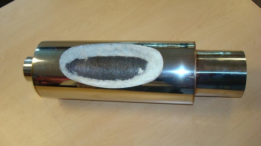
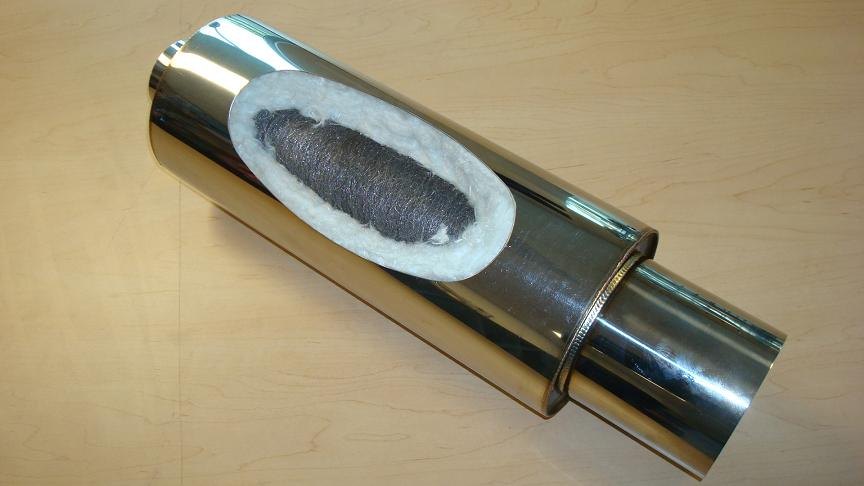
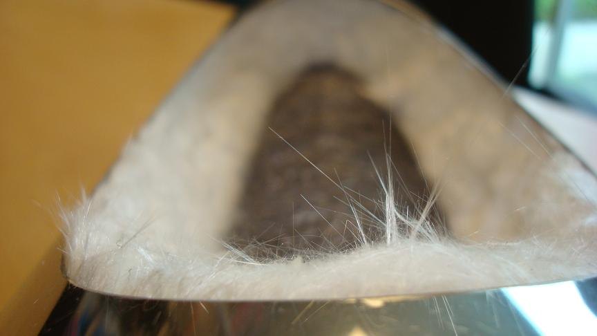
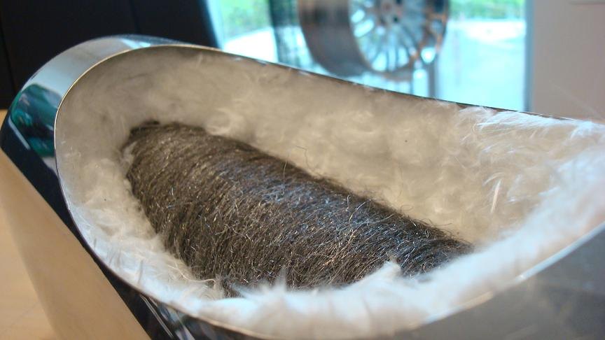
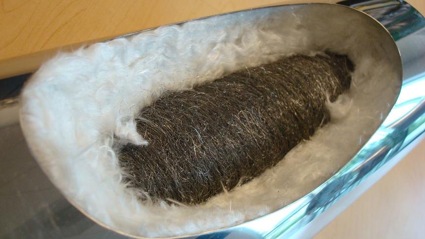
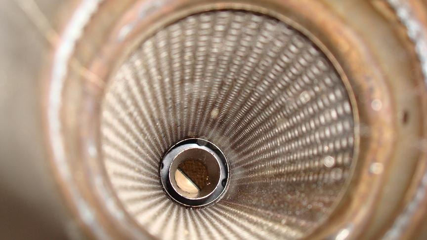
NOTE: The inside view is from the inlet side towards the outlet side. There is a silencer installed in this display muffler.
- Coilover Shock Dyno Plots
-
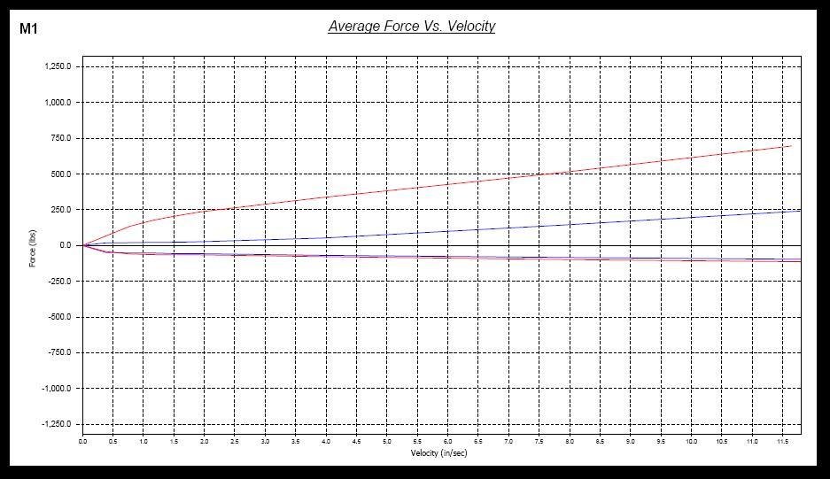
A compilation of shock dynos for Megan Racing coilover line ups.
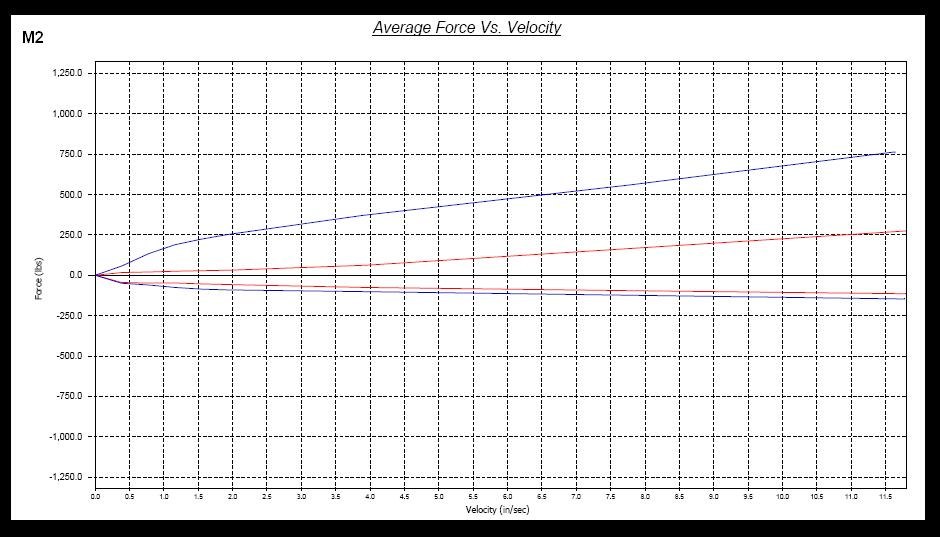
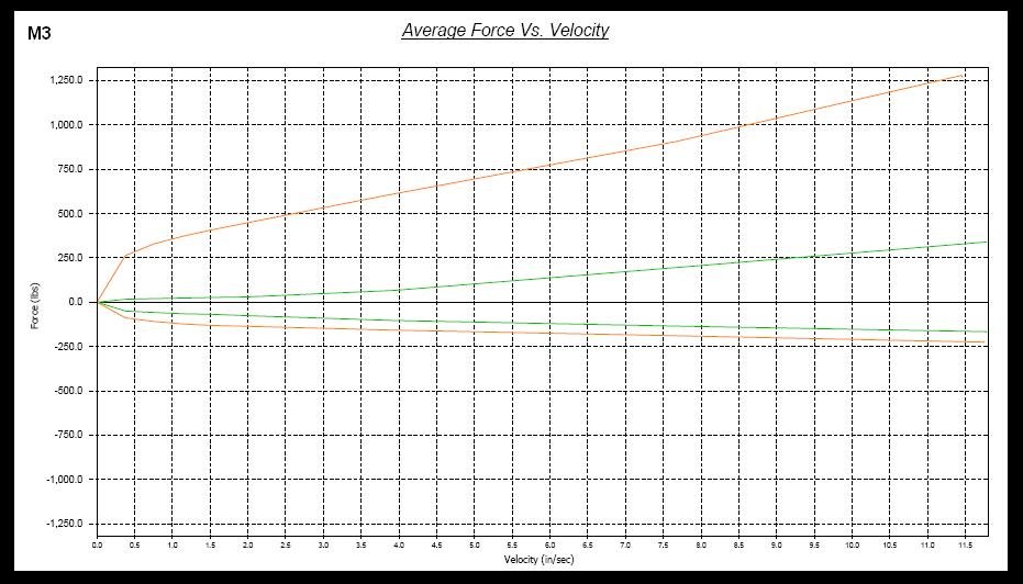
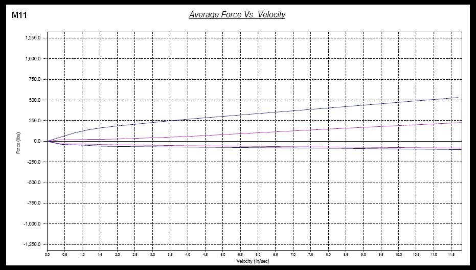
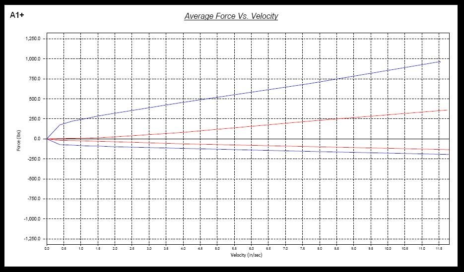
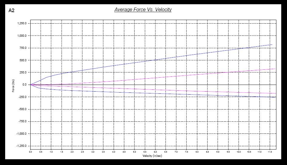
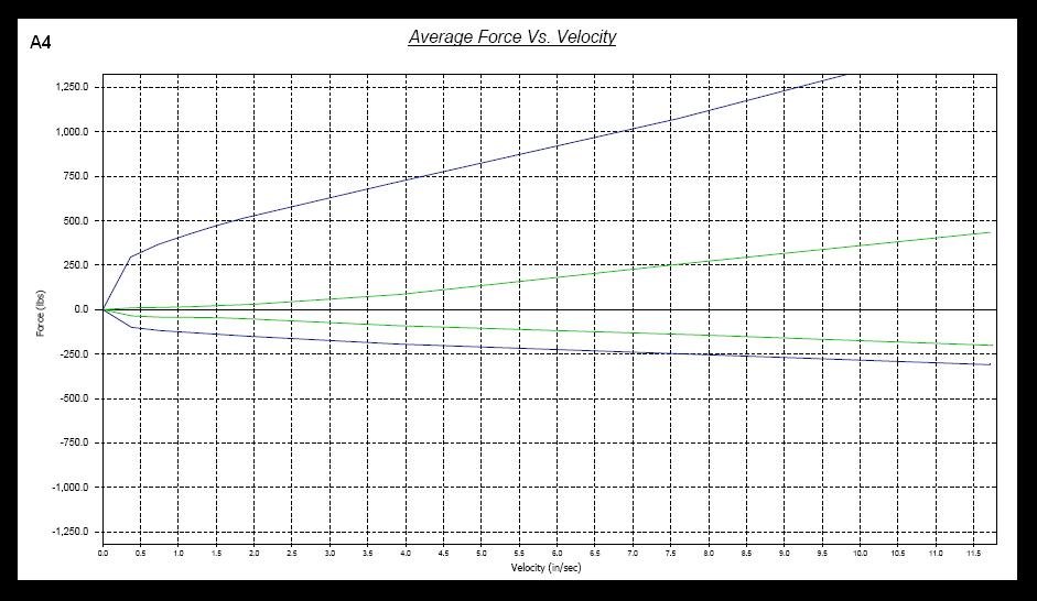
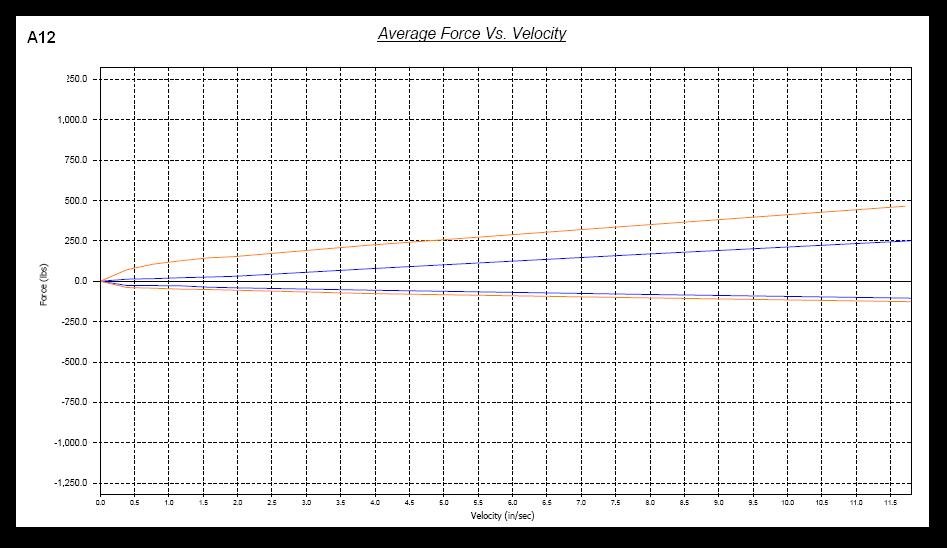
Shock Dynos can give plenty of information about the damper characteristics of each shock. They can give information about the spring rate capabilities, the amount of compression rebound settings with each click, as well as an idea of the low speed and high speed characteristics of the shock.
In each product description for each coilover application, the valving codes are listed along with the dimensional specifications of the included shocks for each application. Below are the shock dynos for these specific valving codes. Please check with the product description for your application for specific details.


- Basics of a 4-wheel Alignment
-
Wheel alignment is a critically important aspect of a vehicle and should be addressed whenever the suspension of the car is altered in any way. Even unbolting a shock from the vehicle may throw off the alignment enough to affect the cornering performance of the vehicle as well as the tire life. Whether you are racing against the clock on a road course, or simply commuting in your daily driver, alignment is a necessary aspect of automobile tuning.
A few terms associated with alignments include: camber, caster, toe, steering axis of inclination (SAI), included angle, scrub radius, riding height (also known as static ride height), set back, thrust angle, steering center, and toe out in turns. Many of these terms are not adjustable, however, but are good to know about. Only in some vehicle applications changes can be made. For the purpose of tire wear as a main priority, camber and toe are the most important factors; not all of these terms need to be addressed for a wheel alignment. Even in proper race car setup, all of these terms are addressed in the setup, but not all of them are necessarily adjusted. Let’s go through each term and its definition.
CAMBER:
When camber specifications are determined during the design stage of an automobile, a number of factors are taken into account. The engineers account for the fact that the wheel alignment specifications used by alignment technicians are for a vehicle that is not moving. On many vehicles, camber changes with different road speeds. This is because aerodynamic forces cause a difference between the riding height and the height of a vehicle at rest. Because of this, riding height should be checked and problems corrected before setting camber. Camber specs are set so that when a vehicle is at highway speed, the camber is at the optimal setting for minimum tire wear.
For many years the trend has been to set the camber from zero to slightly positive to offset vehicle loading, however the current trend is to slightly negative settings to increase vehicle’s stability and improve handling. The camber is the angle of the vertical plane the wheel and tire creates, perpendicular to the horizontal ground. Typical camber settings on factory vehicles range from 0 degrees to 1 degree negative camber. The degree or so of negative camber helps maintain the contact patch of the tire under cornering loads.
On race car applications, it is not uncommon to see larger amounts of negative camber due to different tire compounds utilized that favor maximum tire grip and traction levels over tire wear and longevity. There are no "set-in-stone" camber settings for any application or vehicle as the design of the suspension geometry of the vehicle is just as important as the tire compound being used. A tire pyrometer is often used by race teams to measure the tire tread temperatures on the inner, middle and outer tread blocks after coming in from a hot lap. If you take a cool down lap, tire temperatures are bound to decrease and therefore the data you collect would be inaccurate. The tire temperatures are taken on all four corners, starting from the hotter side first as tire temperatures drop dramatically. The differences between the inner, middle and outer tread blocks can help determine if more camber is necessary to keep the tire from rolling over, or if the camber is setup appropriately. The relative tire temperatures on all four corners are also taken into consideration for further suspension tuning diagnosis, as well as driver inputs. For example, if the front tire temperatures are higher than the rear, it may indicate a "push" situation where the car is understeering, which can point to poor suspension setup, as well as bad driver inputs (overdriving the vehicle and/or setup). In contrast, if the rear tires are higher than the front, it can denote an oversteer scenario, where the driver may need to lay off the throttle.
CASTER:
Positive caster improves straight line tracking because the caster line (the line drawn through the steering pivot when viewed from the side) intersects the ground ahead of the contact patch of the tire. Just like a shopping cart caster, the wheel is forced behind the pivot allowing the vehicle to track in a straight line.
If this is the case, then why did most cars have negative caster specs prior to 1975? There are a couple of reasons for this. In those days, people were looking for cars that steered as light as a feather, and cars back then were not equipped with radial tires. Non-radial tires had a tendency to distort at highway speed so that the contact patch moved back past the centerline of the tire (Picture a cartoon car speeding along, the tires are generally drawn as egg-shaped). The contact patch generally moves behind the caster line causing, in effect, a positive caster. This is why, when you put radial tires on this type of car, the car wanders from side to side and no longer tracks straight. To correct this condition, readjust the caster to positive and the car should steer like a new car.
In a passenger vehicle, caster is not as important as camber and toe settings, but is something to consider, especially in McPherson strut applications, where struts are used in the front suspension as opposed to double wishbone or other multi-link suspension setups. In McPherson strut setups, higher positive caster numbers can help with straight-line stability. These caster numbers are also adjusted to influence the way the vehicle reacts in motorsports. For example, in drifting, higher caster numbers are generally favorable to aid in centering the steering wheel between directional transitions. In racing, caster numbers can influence high-speed straight line stability.
TOE:
Like camber, toe will change depending on vehicle speed. As aerodynamic forces change the riding height, the toe setting may change due to the geometry of the steering linkage in relation to the geometry of the suspension. Because of this, specifications are determined for a vehicle that is not moving, based on the toe being at zero when the vehicle is at highway speed. In the early days prior to radial tires, extra toe-in was added to compensate for tire drag at highway speed.
On some older alignment machines, toe-in was measured at each wheel by referencing the opposite wheel. This method caused problems with getting the steering wheel straight the first time and necessitated corrective adjustments before the wheel was straight. Newer machines reference the vehicle's centerline by putting instruments on all four wheels.
For optimal tire wear settings, where tire conservation is the top priority, zero toe is ideal as the tires will be traveling parallel to each other, producing the least tire drag and rolling resistance. Toe can be set "in" or "out" as well to influence the vehicle's behavior in motorsports use. For example, in front-wheel-drive vehicles, which tend to have problems with understeer, toe-out is used to help promote proper "turn-in" at corner entry. Of course, these settings will always have compromises as a toe-out alignment may cause a twitchy steering wheel at high speeds. Likewise, for rear-wheel drive vehicles that are very oversteer-prone, so tuners may dial in some toe-in in the rear wheels to add some rear end stability.
Steering Axis Of Inclination (SAI)
SAI is the measurement in degrees of the steering pivot line when viewed from the front of the vehicle. This angle, when added to the camber to form the "included angle" (see below) causes the vehicle to lift slightly when you turn the wheel away from a straight ahead position. This action uses the weight of the vehicle to cause the steering wheel to return to the center when you let go of it after making a turn. Because of this, if the SAI is different from side to side, it will cause a pull at very slow speeds. Most alignment machines have a way to measure SAI, however it is not separately adjustable. The most likely cause for SAI being out is bent parts which must be replaced to correct the condition. SAI is also referred to as KPI (King Pin Inclination) on trucks and old cars with king pins instead of ball joints.
INCLUDED ANGLE:
Included angle is the angle formed between the SAI and the camber. Included angle is not directly measurable. To determine the included angle, you should add the SAI to the camber. If the camber is negative, then the included angle will be less than the SAI, if the camber is positive, it will be greater. The included angle must be the same from side to side even if the camber is different. If it is not the same, then something is bent, most likely the steering knuckle.
- Are Megan Racing exhaust products street-legal?
-
All Megan Racing exhaust and suspension products are deemed for "off-road use only". Please check local laws regarding the modification of the exhaust systems by checking the vehicle code for your state. Many states are more stringent on exhaust modification laws and to pass Smog, please check local laws. The following information pertains to California residents:
California's Laws Regarding Modified Exhaust:
CA. V.C. 27151 No person shall modify the exhaust system of a motor vehicle in a manner which will amplify or increase the noise emitted by the motor of such vehicle so that the vehicle is not in compliance with the provisions of Section 27150 or exceeds the noise limits established for the type of vehicle in Article 2.5(commencing with Section 27200) of this chapter. No person shall operate a motor vehicle with an exhaust system so modified.
This shows that there are other characteristics that the exhaust system must conform to truly show a violation. This also shows that other vehicle codes must be considered when in violation of this vehicle code.
CA. V.C. 27150 (a) Every motor vehicle subject to registration shall be equipped with an adequate muffler in constant operation and properly maintained to prevent any excessive or unusual noise, and no muffler or exhaust system shall be equipped with a cutout, bypass, or similar device.
(b) Except as provided in Division 16.5 (commencing with Section 38000) with respect to off-highway motor vehicles subject to identification, every passenger vehicle operated off the highways shall at all times be equipped with an adequate muffler in constant operation and proper maintained so as to meet the requirements of Article 2.5 (commencing with Section 27200), and no muffler or exhaust system shall be equipped with a cutout, bypass, or similar device. (c) The provision of subdivision (b) shall not be applicable to passenger vehicles being operated off the highways in an organized racing or competitive event conducted under the auspices of a recognized sanctioning body or by permit issued by the local governmental authority having jurisdiction.
Part (a) states that the muffler must suppress any excessive or unusual noise. This refers to part (b) which states that the muffler must meet the requirements of Article 2.5, which refers to noise levels. Part (a) and (b) also refer to a cut-away, bypass or similar device commonly known as a "dump."
CA.V.C. 27200(a) The Department of Motor Vehicles shall not register on a dealer's report of sale a new motor vehicle, except an off-highway motor vehicle subject to identification as provided in Division 16.5 (commencing with Section 38000), which produces a maximum noise exceeding the applicable noise limit at a distance of 50 feet from the centerline of travel under test procedures established by the Department of Highway Patrol.
(b) The Department of Motor Vehicles may accept a dealer's certificate as proof of compliance with this article. (c) Test procedures for compliance with this article shall be established by the Department of the California Highway Patrol, taking into consideration the testing procedures of the Society of Automotive Engineers.
- Why do I hear noise from coilovers?
-
Megan Racing has designed a minimalist coilover design that is easy to adjust and tighten, limiting the amount of hardware that may potentially become loose over time. With only a 17mm nut at the very top of the shock shaft to maintain its torque specification aside from the 3 locking spring perches in most applications, there is nothing difficult about diagnosing noise issues with the coilovers.
The noise that occurs from aftermarket coilovers is more prevalent on McPherson strut suspension lay-outs since the entire strut assembly moves along with the hub/knuckle and the drive wheels, when the steering wheel is turned by the driver. All of the rotating forces that result from steering are transmitted through the coilover assembly in a McPhersono strut lay-out, and when combined with the cornering loads on top of the rapid oscillation from bumps and dips in the road, there is no preventative maintenance to keep the shock body and spring perches from getting loose besides regular maintenance which is as simple as checking the coilovers to make sure they are tight periodically. While it is good practice to do the same for double-wishbone suspension lay-outs, it is not necessary as double-wishbones do not turn the shock body when the steering wheel is turned.
There are two typical noises that result from coilovers:
- The first typical noises are commonly described as "rattling" and "clunking."
- The second typical noise from coilover assemblies is "coil-bind."
"Rattling" and "Clunking"
Rattling and clunking usually sound like metal-to-metal contact and usually are sharper, more direct noises. This first issue is caused by loose components of the coilover assembly. The best way to diagnose this type of noise is to make sure all of the components of the coilover assembly are tightened.
1) First, you must understand that the entire "coilover assembly" is built around the shock body. The lower bracket is threaded onto the threaded shock body, and locked in place by a single locking spring perch. On the piston shaft of the shock, there is a bumpstop and dust boot. The spring is held in place by two locking perches (locked against each other) on the shock body. Above the spring is the upper spring mount. On top of that is the pillow-ball upper mount, which has the lower and upper pillow-ball bearing surrounding it. The pillow-ball mount is usually incorporated into the top hat, which has the studs built in that bolts through the chassis holes. On McPerson strut applications, the pillow-ball mount is mounted onto the camber plate.
2) Now that you are aware of the miscellaneous parts of a coilover assembly, this first noise is usually caused by either the locking perches on the shock body being loose, or any of the components above the spring, which are all secured in place on the shock shaft by a single 17mm nut. To access the top 17mm nut, you must remove the damper adjustment knob which is simply threaded onto the very tip of the shock shaft.
3) To tighten the 17mm nut, after the removal of the damper adjustment knob, the top of the shock shaft will be exposed. You will notice there is a 6-sided shape within the top of the piston shaft, which is to be used for a hex tool of the appropriate size. All of Megan Racing coilover damper kits come with this hex tool for this very purpose (as well as to tighten the camber plate allen head bolts for strut applications). Using a closed-end wrench along with this hex tool, tighten the 17mm nut. The typical torque specification for an automotive 17mm bolt is about 40-60 lbs/in. This is a good baseline to aim for, but the critical part to take notice of is to make sure that as you are tightening the 17mm bolt, the shock shaft is not rotating with the nut otherwise, the nut is not actually getting tightened. It is also a good safeguard to use an impact gun after the hex tool and wrench were used to assure that the assembly is tightened up to spec.
NOTE: Remember to torque the top 17mm nut at the top of all McPherson struts to 40-60ft/lbs with properly calibrated torque wrench. Improper torque specification can cause the assembly to come loose and cause symptomatic clunking noise, or may damage the threads on the shock shaft when overtorqued. The "crash bolts/eccentric bolts" holding the lower steel bracket onto the knuckle also needs specific torque specs. You will need to follow the OEM torque specifications for these bolts. Torque specifications for these bolts are critical to the safe operation of your coilovers on you vehicle. It is recommended to double check these torque specs with the vehicle manufacturer. Please replace the bolts with brand new OEM hardware once torqued down to specification. Due to the nature of these bolts and the excessive loads they experience, these bolts will stretch after repeated use, rendering the possibility of hardware failure. These are one-time-use only bolts. Failure to do so will void certain warranty applicability.
"Coil-Bind"
Coil-bind is only found on McPherson strut applications due to the nature of the strut design. Coil-bind is a "springy" noise that only occurs at low speeds while turning the wheel. Typically, coil-bind is usually experienced for example when maneuvering at slow speeds in a parking lot, where speeds are low and there are a lot of steering angle inputs. The "springy" noise is distinct from the sharper, more direct noises that occur when the assembly is loose and a component is rattling and clunking around from the miscellaneous loads stressed upon the coilover assembly.
Many times, coil-bind is difficult to diagnose and fix. Some vehicles experience this more than others, and it is not a brand-specific issue. A coilbind remedy Megan Racing suggests to apply grease to the upper and lower spring isolators, also referred to as noise prevention cushions. Grease should also be applied to the lower and upper pillow-ball bearing. This step may require disassembly of the entire coilover unit.