
Instructions
- Wheel Hub Replacement
- Bearing Replacement
- Checking
Hub Unit Bearing Removal
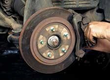
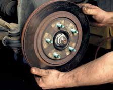
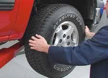
1. Raise vehicle and remove lug nuts and wheel.
2. Remove the brake caliper and rotor. Support the brake caliper with an “S” hook or a piece of wire.
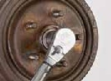
3. Remove the axle nut, using an axle nut socket. Follow the manufacturer’s instructions for nut replacement.
4. Before removing hub unit, make a note of the proper orientation and positioning of the sensor wire and bearing. Disconnect the ABS sensor wire from its mating connector point and positioning clips.
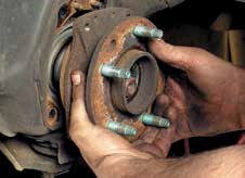
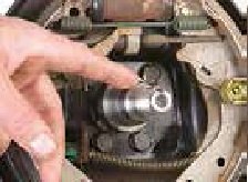
5. Remove the steering knuckle attachment bolts. You may need a puller to remove the hub assembly. Do not damage the knuckle or axle shaft.
6. Clean and inspect the steering knuckle. Remove any debris, nicks or burrs using a fine file, wire brush, emery cloth or honing stone.
Hub Unit Bearing Installation
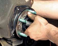
1. Insert the new hub assembly into the steering knuckle. Check the positioning of the splines on the axle shaft while inserting the hub assembly. Never force the hub assembly on the shaft or strike with a hammer.
2. Torque the knuckle-bearing mounting bolts to the vehicle manufacturer’s specification using a torque wrench. Do not use an impact wrench.
3. Connect the new ABS sensor that comes already attached to the new bearing to its mating connection point and clips in the wheel well and frame area.
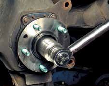
4. Install the axle nut. Tighten the nut to the vehicle manufacturer’s torque specification using a torque wrench. Do not use an impact wrench.
5. Replace the brake rotor and brake caliper. All wheel components should be clean from debris and burrs.
6. Replace the wheel and torque the lug nuts. Follow the vehicle manufacturer’s recommendations regarding torque specification and re-torque requirements.
Replacing tapered single-row wheel bearings in passenger cars and light trucks.
Proper wheel bearing removal and installation helps avoid premature damage to bearings and surrounding components.
1. Wheel End Disassembly
Follow the vehicle manufacturer’s recommended procedure to remove the tire and wheel assembly, disk brake caliper, dust cap, cotter pin, adjusting nut and washers. Pull the rotor/hub assembly toward you to loosen the outer bearing cone assembly. Remove the outer bearing cone assembly. Pull the rotor/hub assembly off the spindle - the inner bearing cone assembly, inner cup, outer cup and seal will come with it. Use a seal puller to remove the seal, then remove the inner bearing cone assembly from the rotor/hub. Discard the seal after removal. Use a cup driver or mild steel bar to remove the inner cup and the outer cup from the hub assembly.
2. Clean and Inspect Hubs and Spindles
Remove all old lubricant from the rotor/ hub assembly and spindle. Clean the rotor/hub assembly and spindle with kerosene or mineral spirits. Inspect the spindle for wear. Use a fine file, wire brush, emery cloth or honing stone to remove any debris, nicks or burrs. Follow the vehicle manufacturer’s recommendation for permissible spindle wear. Apply a light grease coating on the cone seats to ease installation and prevent fretting.
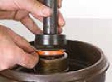
3. Install cups
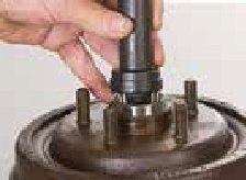
Use a cup driver or mild steel bar to drive the new inner cup and outer cup into the hub/ rotor assembly until solidly seated against the hub shoulders. Be careful not to damage the cup surfaces. Never use a bearing cone assembly to drive a cup.

4. Lubricate
Use a mechanical grease packer to pack the inner bearing cone assembly with grease. Place the bearing cone assembly, small end down, into the grease packer funnel. Plug the bore of the large end of the bearing cone assembly with the conical retainer. Firmly press down on the conical retainer. This forces the grease between the rollers, cage and cone. Smear excess grease on the outside of the bearing cone assembly. Pack grease between the inner and outer cups in the hub cavity. Also, liberally coat the hub cap inner wall. This layer combats moisture and retains the grease in the inner and outer bearing cone assemblies.
5. Install Grease Seal
Replace the grease seal when it leaks or when bearings are being repacked or replaced. Install the inner bearing cone assembly in the hub, then install the new seal. Make sure the seal lips are pointed in the right direction following the vehicle manufacturer’s specification. Use the proper seal installation tool.
6. Install Rotor/ Hub Assembly
Be careful not to damage the seal against the spindle when sliding the rotor/hub assembly back over the spindle. After following Step 4, pack the outer bearing cone assembly with grease. Install the outer bearing cone assembly, washer and adjusting nut on the spindle.
7. Bearing Adjustment
Use a torque wrench to tighten the adjusting nut to 50 ft. lbs. while turning the rotor. Back off the adjusting nut 1 full turn. Retorque the nut to 10 ft. lbs. while turning the rotor. Next, back off the adjusting nut ¼ turn. Lock the nut with a new cotter pin.
8. Check Bearing Adjustment
Use a dial indicator to measure endplay. Mount the indicator base as close to the center of the hub/ rotor as possible. With the indicator tip against the end of the spindle, set the indicator at zero. Grasp the rotor at three o’clock and nine o’clock. Push the rotor in while oscillating and read the dial indicator. Pull the rotor out while oscillating and read the dial indicator again. The bearing endplay is equal to the total indicator movement, which should be between 0.001” and 0.005.” If not, repeat steps 7 and 8. Reinstall all components as the vehicle manufacturer recommends.
This information will help you to recognize common causes of wheel noise.
1. Verify the source of any unfamiliar noise: Road surface conditions, tire tread design, wear patterns, and improper maintenance conditions including poor alignment and worn suspension parts.
2. Make sure you have the proper tools.
3. Perform a full hand rotation check on the wheel. Grasp the wheel at the 3 and 9 o’clock positions. Push and pull while oscillating the wheel. Perform a second check, grasping the wheel at the 12 and 6 o’clock positions. Listen and feel for roughness.
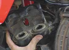
4. Remove the lug nuts and the wheel. Remove the caliper from the caliper-mounting bracket. Support the caliper with an “S” hook or a piece of wire.
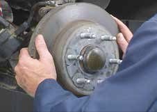
5. Remove the caliper-mounting bracket and the brake rotor from wheel hub.
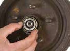
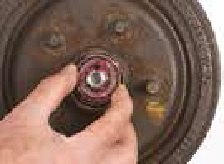
6. Rotate the hub bearing assembly by hand. A loose hub bearing assembly may indicate bearing damage, the axle nut may have backed off, or improper axle nut clamping. Roughness, looseness or noise from the bearing is an indication of bearing damage and requires replacement.
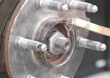
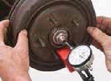
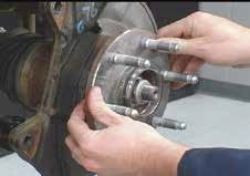
7. Check the hub bearing assembly’s internal clearance using a dial indicator with a magnetic base. For an accurate reading, thoroughly clean and smooth the surfaces where you will place the dial indicator base and tip. Use a fine file, wire brush, emery cloth or honing stone as appropriate to remove any debris, nicks or burrs.
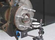
8. Place the dial indicator base on the knuckle or a secure portion of the suspension. When setting the dial indicator tip, the indicator itself should have ample travel for the variation around the face. Position the indicator tip perpendicular on the wheel pilot as close to the center of the hub bearing assembly as possible to provide the most accurate results.
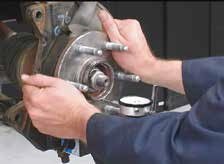
9. Grasp the wheel flange at the 3 and 9 o’clock positions, and push while oscillating the hub bearing assembly approximately 90° side-to-side at least five times. Set the dial indicator to zero. Next, pull while oscillating the hub bearing assembly approximately 90 degrees side-to-side at least five times. Proper loading and oscillation is necessary to fully seat the bearings.
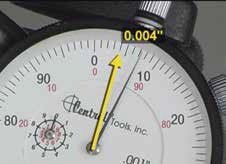
10. Observe the total indicator movement. If it exceeds 0.004”, replace the hub bearing assembly.